Description
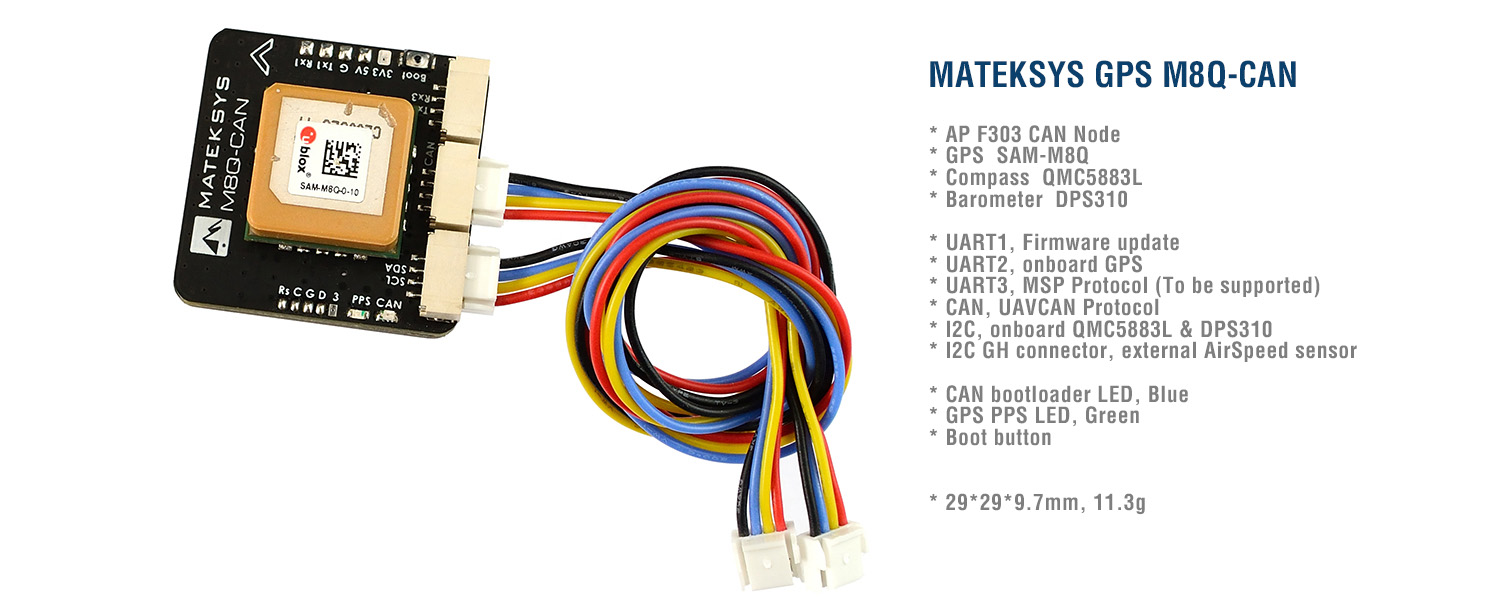
MATEK GPS M8Q-CAN, UAVCAN
SPECIFICATIONS
- ArduPilot AP_Periph F303 CAN node
- GPS SAM-M8Q (GPS, GLONASS, Galileo)
- Magnetic Compass QMC5883L
- Barometer DPS310
- UART1, Firmware update
- UART2, onboard GPS
- UART3, MSP Protocol (To be supported)
- CAN, UAVCAN Protocol
- I2C, onboard QMC5883L & DPS310
- I2C JST-GH connector, external AirSpeed sensor
- CAN bootloader LED, Blue
- Fast blinking, No communication between CAN node and Flight Controllers
- Slow blinking, Communicating between CAN node and Flight Controllers
- GPS PPS LED, Green
- blinking(1Hz) when GPS has 3D fixed
- Boot button
- Input voltage range: 4~6V
- Power consumption: 100mA
- Operating Temperatures: -20~80 °C
- 29mm*29mm*9.7mm
- 11.3g
INCLUDES
- 1x M8Q-CAN
- 2x JST-GH-4P to JST-GH-4P 20cm silicon wire
TIPS
- u-blox M8Q series has no external flash memory
- Compass Alignment(Arrow forward and flat mounting):
Ardupilot/Mission Planner: Rotation None - Make sure to have compass/magnetometer 10cm away from power lines/ESC/motors/iron based material
- The scratches on ceramic antenna are the result of tuning the antenna by ublox.
- UART3 MSP Protocol is not implemented for now.
——————————————————-
WIRING AND AP PARAMETERS
| CAN | I2C | |||
| M8Q-CAN | Flight Controller | M8Q-CAN | I2C Airspeed sensor | |
| 5V | 5V | 5V or 3V3 | check AirSpeed sensor voltage spec. | |
| C-H | CAN High | SCL | SCL | |
| C-L | CAN Low | SDA | SDA | |
| G | GND | G | GND | |
| CAN_D1_PROTOCOL | 1 | |||
| CAN_P1_DRIVER | 1 | |||
| GPS_TYPE | 9 (UAVCAN) | ARSPD_TYPE | 8 (UAVCAN) | |
| COMPASS_TYPEMASK | 0 (make sure UAVCAN Unchecked) | ARSPD_USE | 1 | |
*** You must set CAN Node parameters for airspeed sensor connected to I2C port of M8Q-CAN ***
Mission Planner->Initial Setup->Optional Hardware->UAVCAN-> SLCan Mode CAN1 -> Parameters
- MS4525 ARSP_TYPE -> 4
- MS5525 ARSP_TYPE -> 3
- SDP3X ARSP_TYPE -> 6
- DLVR-L10D ARSP_TYPE -> 9
- Write and reboot
PINOUT & PADS
| GH-4P Pin | Signal | Wires color | Pads | Signal | |
| 5V | 4~6V input | Red | 3V3 | onboard LDO output | |
| C-H | CAN high | Yellow | 5V | 4~7V input | |
| C-L | CAN low | Blue | G | GND | |
| G | GND | Black | Tx1 | UART1-TX | |
| Rx1 | UART1-RX | ||||
| 5V | 4~6V input | Red | Rs | F303 NRST | |
| SCL | I2C-SCL | Yellow | C | F303 SWCLK | |
| SDA | I2C-SDA | Blue | G | GND | |
| G | GND | Black | D | F303 SWDIO | |
| 3 | onboard LDO output 3.3V | ||||
| 5V | 4~6V input | Red | |||
| Tx3 | UART3-TX | Yellow | |||
| Rx3 | UART3-RX | Blue | |||
| G | GND | Black | Boot button | Bridge Boot to 3.3V |


Reviews
There are no reviews yet.